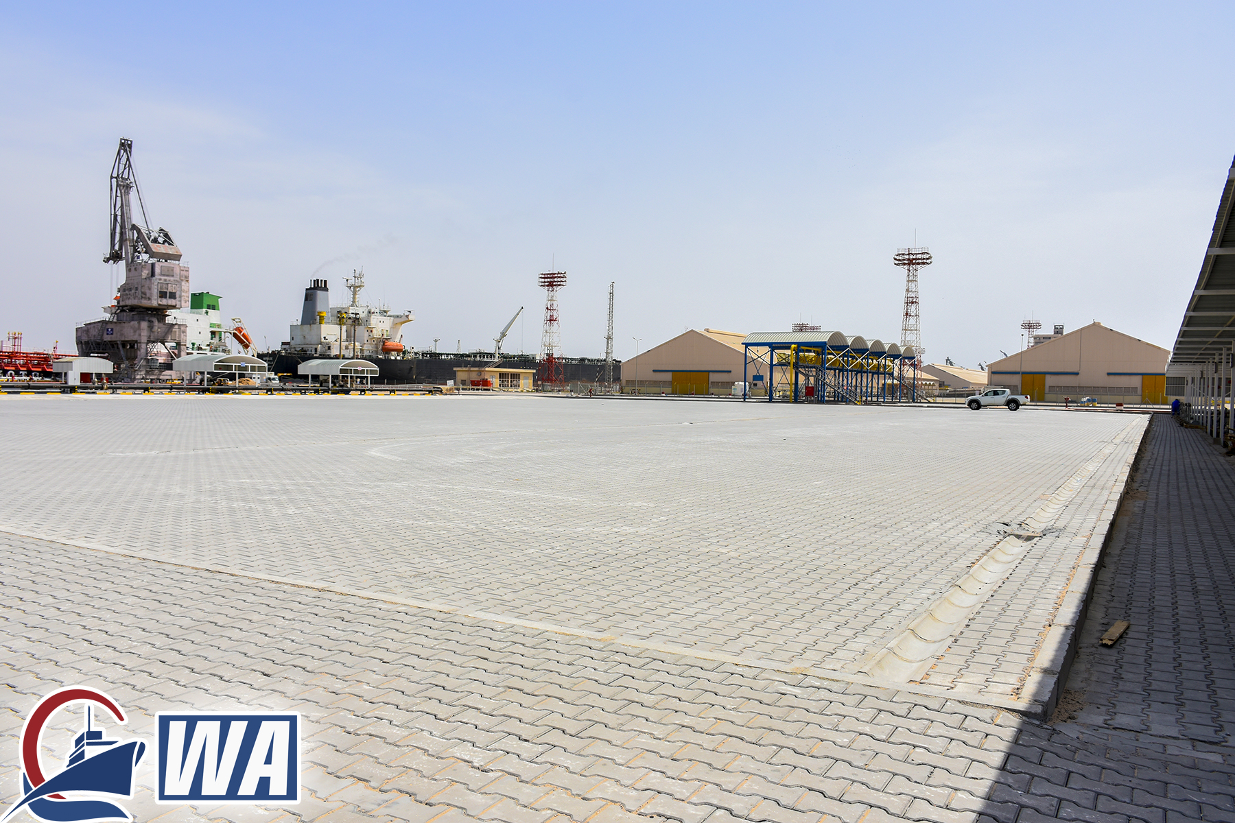
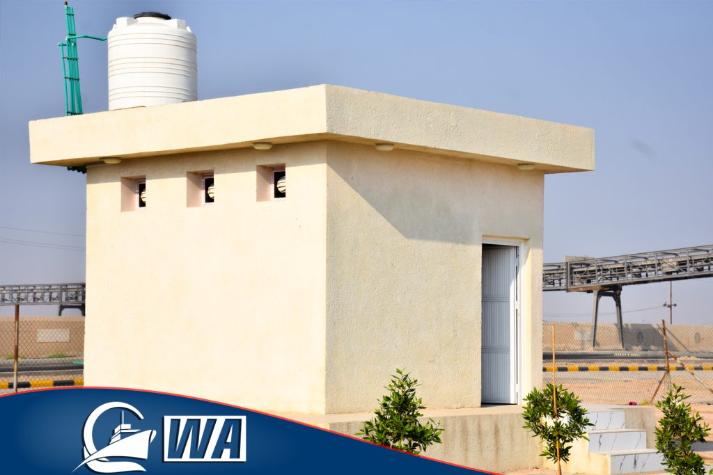
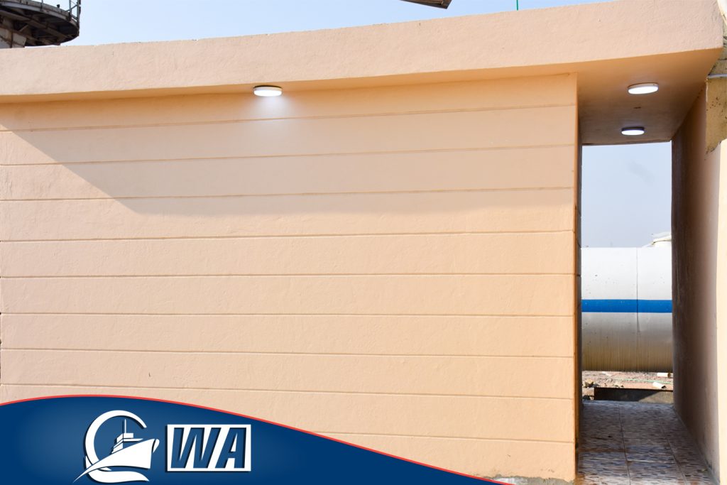
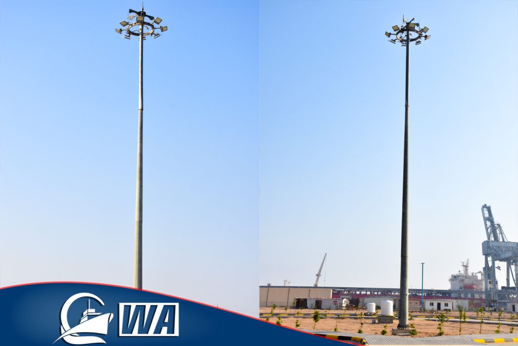
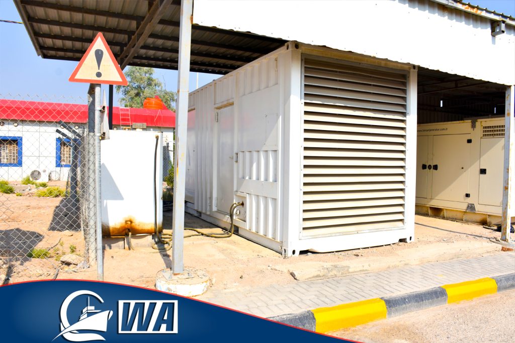
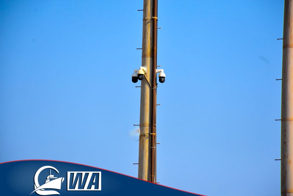
Rehabilitation

Description of equipment and Establishments on site

1- Platform for loading gasoline and gas oil
* This Platform includes an iron roof with (8″) diameter pipes, loading holes, and (10) ten counters for commercial accounting.
 * The loading platform can received (10) fuel tankers in one time, and managed by a qualified cadre.
* The Platform is protected by a foam extinguishing system in addition to a small fire extinguisher with a capacity of (12) kg.
* The Platform is protected by a grounding system (ground) for the generated static electricity.
* The Platform is connected to the system for discharging surpluses and distillates through measuring tubes (4”).
2- NAPHTHA DISCHARGE AND RECEIVING SYSTEM
* Composed of three specialized pumps for light hydrocarbon liquids with a head (compound) for suction and another for pushing (8″).
* The material receiving the products from the truks are (20) slots measuring (2.5″) equipped with rubber hoses and ball valves.
* A main pipe to push the product to the berth (10B) branching at the quay into two branches with a distance between them (80 meters) with ball valves of diameter (8″) on each branch and two hoses (2) for each opening of the hose length (15 meters).
* Total lengths of pipes measuring (8″) up to (150) meters.
* The pumps and the collector( Pipe) are located inside a ground concrete basin with dimensions (90X10X1) m3.
*There is a control room for the pumps that includes  three electrical operating panels with the necessary electrical protection devices.
3- Heavy Fuel oil export system (fuel oil)
It includes the following:
* Four electric screw pumps with capacities (500 x 2 m3/h) + (250 x 2 m3/h)
* Tubular intake header: (14″) has (29) 2.5″ double manifolds with hoses and ball valves.
* Tubular collector  header: (12″) with control valves and branching into two branches towards the berth (10A-10B) (10″).
* Total lengths of pipes measuring (10″) up to (150 meters)
* A concrete yard with dimensions (84 m x 15 m) for the purpose of parking the trucks during unloading, for receiving  (29) trucks  with a load of (30) tons.
* On-site operation and control panels for the electrical power of these pumps according to their design capacities with the necessary electrical protection means.
* The power supply panel (Cables  link box) is central within the aforementioned yard
4- ELECTRIC POWER SUPPLY UNIT
* Box conversion unit (Kiosk) with a capacity of (2000KV) and equipped with automatic switches (CB) on both ends of the high pressure and low pressure / conversion system (11KV/400V).
* This unit feeds all the facilities of site (A) with power and is connected to the main power station (Japanese station) at the site at the mobile station (with transfer 33/11)
* All pumps are equipped with control, operation and protection units, and they are connected to the pumps through cables of different capacities (6X150 mm2) + (6X240 mm2) + (6X50 mm2).
* The floor for handling and movement of cars is leveled and paved with stone (Type c5)

Safety and Fire System For the Site

Fire detection and alarm devices

All rooms and offices on site include fire detectors and alarms

Fire water tanks

The site contains (6) firefighting water tanks, each capacity (50 m3) with a total capacity of (300 m3), made of iron and installed on a concrete base and asphalt layer connected to each other through a pipe measuring (14″) connected to the pumps intake manifold.

Firefighting system

* Electric control panels and control room dimensions (5 x 4) m 2
* The main fire network pipe measuring (8″) with a length of (1200 m) and there is a part of the pipe covering the area (A1) with a length of (300 m) and an additional size of (6″) surrounding the product handling systems of the trucks
* There are (22) fire nozzles and foam cannons distributed on the berths and yards.
* There are metal cabinets (boxes) to keep fire hoses containing the number of extinguishers (hoses + mixers)

Fire pumps

The site is equipped with fire pumps consisting of the following:
* One (1) main electric firefighting pump with a capacity of (290 m3/h), where the water pushing force of the main electric pump reaches (12 bar).
* Electric firefighting pump to maintain network pressure (jockey) number (1) with a capacity of (15 m3/h) the power of the jockey pump to push water (3 bar)
* Diesel emergency backup pump with a capacity of (290 m3 / h) and the force of water pushing up to (14 bar).

FOAM TANK

THE SYSTEM CONTAINS TWO FOAM TANKS (TYPE AFFF) COVERING THE ENTIRE SITE AREA:
* ONE TANK CONTAINING A CONCENTRATED FOAM CAPACITY OF (3000 LITERS) OF THE TYPE (AFFF), WHICH MIXES WITH WATER TO FORM A FOAM THAT PREVENTS OXYGEN FROM REACHING THE FIRE. THE TANK IS LOCATED WITHIN THE(A1) YARD IN THE AREA OF OIL DERIVATIVES HANDLING PLATFORMS BY TANK CARS.
* AND THE OTHER TANK CONTAINING CONCENTRATED FOAM OF TYPE WITH A CAPACITY OF (5000 LITERS) LOCATED ON BERTH 11 NEAR THE PLATFORM FOR UNLOADING GASOLINE FROM MARINE TANKERS